Circuit Assembly and Chassis Integration
During the Course Labs and IP-1, you will:
Design and build different circuits which perform a certain function together
Design a power supply which will be used to supply the power amplifier with the correct voltage and sufficient power
Build a power amplifier which will drive the filters for the speakers
Chassis Assembly
You will build your system (integrate your subsystems) in an open cabinet (chassis) that includes a bottom, a front, and a back panel
Four feet are mounted on the bottom of the chassis to prevent scratches
You will connect the various subsystems using connectors and soldered connections
Aim for neatly routed wires and take care to prevent stability/robustness issues that can surface at unexpected times and may be difficult to debug
An example of such a chassis can be seen in Figure 1
Connectors
The following connectors can be mounted onto the front and back panels of the chassis:
BNC chassis connectors,
3-mm stereo jack-plugs,
chassis banana plugs,
6-mm LEDs (red, green and yellow) with mounting rings,
switches to turn on and off small circuits.
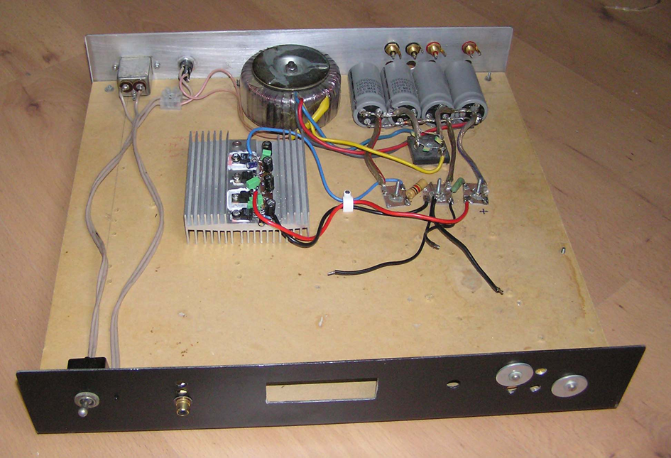
Figure 1:Examples of the IP-1 chassis for the mounting of test circuits.